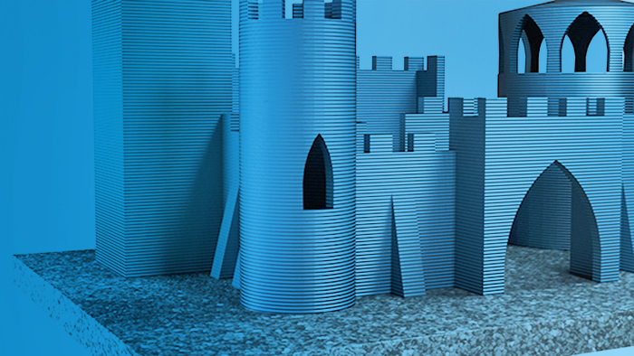
More sizes. More materials.
Create large volume prints and components in a wide range of materials with FTC 3D.
The FTC 3D process
FTC 3D GmbH has developed a new 3D printing process which combines a number of 3D printing techniques to produce large volume components significantly faster and more efficiently.
Solid and liquid components are combined to produce a highly viscous mixture which is then transported to the printhead by the feeder unit and ready for use. The nozzle unit supplies a constant volume of printing medium based on the printing speed and specified level of printing quality. The curing process starts as soon as the medium is extruded from the nozzle and rapidly acquires the strength and structural stability needed for the
RAW MATERIALS
The process can be used with almost any materials which have a specific type of granular structure and respond well to wetting. The size, shape and distribution of the particles are critical. Packing density is also very important in printing media. It is the key to achieving the requisite mechanical strength and preventing the formation of cavities. For this, it is necessary to optimise the ratios of particle sizes. The granulate must combine efficiently with the liquid components to form a homogeneous mixture. The viscosity is adjusted to ensure the printing medium flows correctly and the nozzle receives an adequate supply. This process ensures that the granulates are perfectly aligned with each other during the subsequent stages of the process and form a homogeneous, cylindrical, solid body in the shape of an endless rod. This is extruded from the printhead nozzle at a constant and adjustable speed.
Video
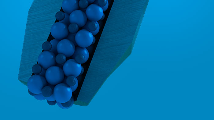
From granulate to endless rod
FTC 3D achieves perfect results with innovative printing technology and the optimum combination of materials.
Chemical reaction
mechanisms
The reaction mechanisms involved in curing the printing medium are almost exclusively based on polyurethane, acrylate and thiol-ene chemistry.
Isocyanate reacts with alcohols to produce urethane
R-N=C=O + R’OH -> R-NH-COO-R’ (urethane)
Isocyanate reacts with amines to produce urea
R-N=C=O + R’NH2 -> R-NH-CONH-R’ (urea)
Isocyanate reacts with water via the formation of the carbamic acid intermediate and splitting off of water to form urea
R-N=C=O + H2O -> R-NH-CONH-R (urea)
Acrylic acid reacts with alcohol to form acrylate
H2C=CH-COOH + ROH -> H2C=COOR
Compounds with reactive double bonds react with thiol to form alkanethiol.
H2C=CHR + R’SH -> R’SCH2CH2R
The polyurethanes and polyureas are generated using the polymerisation reactions described under A - C. In the reactions D - E,
the polymer networks are primarily formed by photocatalytic radical insertion.
Surface curing is based on acrylate systems which undergo a photocatalytic, radical polymerisation reaction using UV LED technology.
At the same time, another reaction mechanism begins curing the interior of the paste rod (multi-cure process).
FTC 3D PRINT UNIT
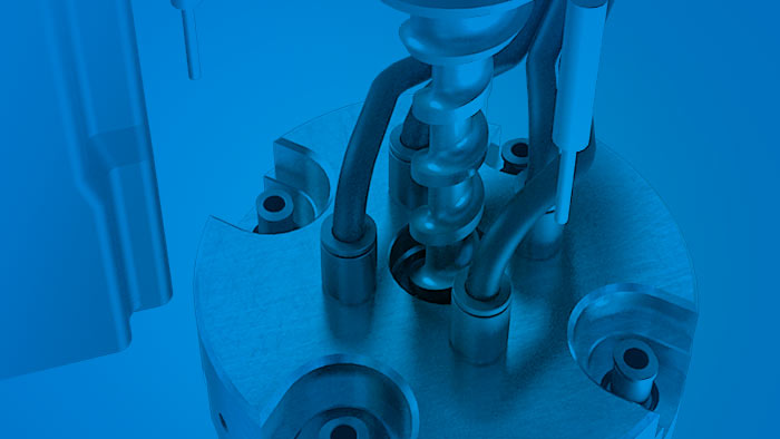
Processing the printing media
The printing media are prepared above the nozzle. An adjustable pump unit transports the media to the printhead nozzle. The reservoir is continuously refilled to ensure an adequate supply of material at all times.
The fill level is monitored. While being transported to the printhead nozzle, the printing media are aligned and compressed to ensure a high packing density with the minimum number of cavities. At the same time, the material is chemically prepared for the rapid surface curing process. A special mechanism upstream of the printhead nozzle ensures that the rod has excellent mechanical strength and is thus capable of withstanding the high printing and shearing forces generated during the application of further layers. Shortly after it has been extruded, the printing medium receives a pulse of energy which initiates the curing process. The thicknesses and widths of the layers are highly dependent on the printing medium and nozzle diameter. These parameters can be adjusted in the slicer software to take account of the type of material and the required surface quality.
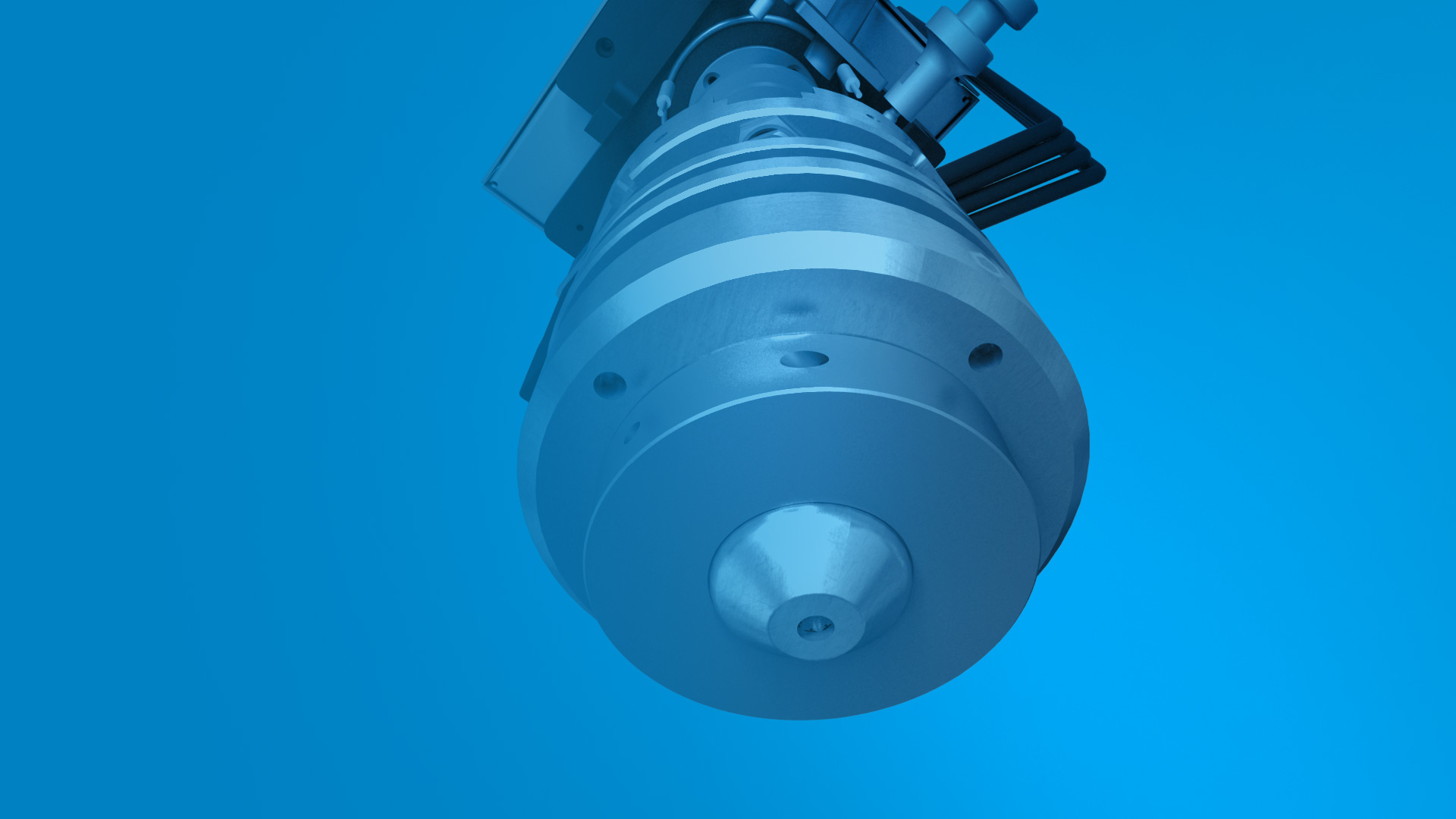
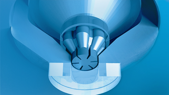
Printhead nozzle diameter
The printhead nozzle diameter can be scaled according to the granulate size. This allows manufacturers to generate large volumes of material and accelerate the production of large components.
The printhead nozzle diameter is adjustable from 3 to 10 mm. The ratio of nozzle diameter to print bed area is worth comparing to current processes – a nozzle diameter of 10 mm is capable of printing an area 25x larger under similar printing conditions.
Software and controls
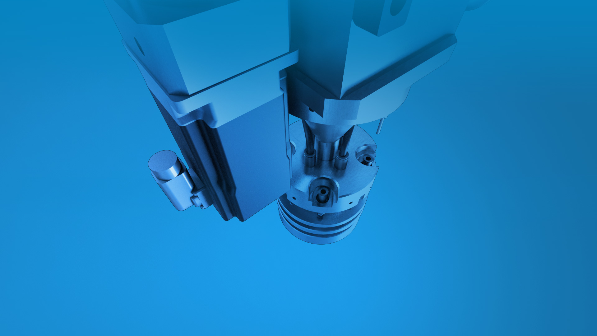
FTC 3D GmbH has developed controlling software to ensure precise coordination of every phase of the process.
The feed rate on the x- and y- axes regulates all the upstream units in combination with the printhead nozzle diameter and the target layer thickness of the printing medium. The mixing, feeding and dosing of the printing medium are key factors in determining the quality of the printed product and critical to the visual appearance of its surfaces. The slicer and post-processor software have been fine-tuned to guarantee precise definition of the processing parameters for the specific printing medium and a high quality printed product. The slicer and post-processor software give the operator full control over all the relevant 3D printing parameters. These are then processed into a control code (primarily as G- and M-code) and transmitted to the machine.
